🎯 Instrumentation Amplifiers: Precision Measurement
We've learned about difference amplifiers. They subtract signals. But they have a problem:
Input impedance is only okay, not great.
When measuring tiny signals from sensors (thermocouples, strain gauges, medical electrodes), you need:
- Very high input impedance (GΩ range)
- Very high CMRR (Common-Mode Rejection Ratio)
- Precise, adjustable gain
- Low noise and drift
This is where Instrumentation Amplifiers (In-Amps) shine.
🔍 What is an Instrumentation Amplifier?
An instrumentation amplifier is a precision differential amplifier designed specifically for measurement applications.
Key Features
| Feature | Regular Diff Amp | Instrumentation Amp |
|---|---|---|
| Input impedance | ~10kΩ to 100kΩ | >1GΩ (both inputs) |
| CMRR | 40-60dB | 80-120dB |
| Gain accuracy | Moderate | Excellent (<0.1% error) |
| Gain adjustment | Multiple resistors | Single resistor |
| DC offset | Higher | Ultra-low |
| Noise | Moderate | Very low |
🏗️ Three Op-Amp Instrumentation Amplifier
The Architecture
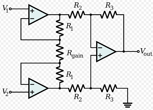
- Input V1 to non-inverting of Op-Amp 1
- Input V2 to non-inverting of Op-Amp 2
- Gain resistor Rg between inverting inputs of Op-Amp 1 and 2
- Resistors R from each output to respective inverting inputs
- Op-Amp 1 and 2 outputs feed difference amplifier (Op-Amp 3)
- Final output Vout
How It Works
Stage 1 & 2: Input buffers with gain
- Very high input impedance (op-amp inputs)
- Differential gain set by single resistor
Stage 3: Difference amplifier
- Subtracts the two buffered signals
- Fixed gain (usually 1)
- Very high CMRR
📐 The Magic Equation
For the three op-amp instrumentation amplifier:
Where:
- = input voltages
- = input stage resistors (matched pair)
- = gain-setting resistor (the only one you change!)
🎚️ Setting the Gain
Want gain of 100?
If :
Use standard value
That's it! One resistor controls the entire gain.
- High gain (100-1000): = 100Ω to 1kΩ
- Medium gain (10-100): = 1kΩ to 10kΩ
- Low gain (1-10): = 10kΩ to 100kΩ or even open circuit
For variable gain, use a potentiometer for !
🌡️ Real-World Example: Thermocouple Amplifier
Problem: K-type thermocouple produces 41µV/°C
Measure temperature range: 0-500°C
Output range needed: 0-5V for ADC
Signal from thermocouple: (500°C × 41µV/°C)
Required gain:
Design:
- Choose (typical)
- Calculate :
Use standard value: (1% tolerance)
Result:
- 0°C → 0V
- 500°C → ~5V
- Perfect for 10-bit ADC (0-1023 counts)
💪 Why Common-Mode Rejection Matters
The Problem
Sensors often pick up noise:
- 50/60Hz mains hum
- EMI from motors, switching supplies
- Ground potential differences
This noise appears equally on both inputs = common-mode signal
Example
What we want:
With poor CMRR (40dB):
- Noise rejection: 100:1
- Remaining noise: 1mV
- Signal: 5µV
- Signal drowned in noise!
With excellent CMRR (100dB):
- Noise rejection: 100,000:1
- Remaining noise: 1µV
- Signal: 5µV
- Clean signal!
🔬 Common-Mode Rejection Ratio (CMRR)
Definition:
| CMRR | Rejection Ratio | Application |
|---|---|---|
| 40dB | 100:1 | Basic measurements |
| 60dB | 1,000:1 | General instrumentation |
| 80dB | 10,000:1 | Precision measurements |
| 100dB | 100,000:1 | Medical, strain gauges |
| 120dB | 1,000,000:1 | Ultra-precision |
CMRR depends on:
- Resistor matching (use 0.1% or better)
- Frequency (CMRR decreases at high frequencies)
- Op-amp quality (use precision op-amps)
- PCB layout (symmetric, short traces)
- Temperature (use low-drift resistors)
⚖️ Wheatstone Bridge + In-Amp = Perfect Match
We'll cover Wheatstone bridges in detail soon, but here's a preview:
Strain Gauge Measurement
Bridge output: Typically ±10mV full scale
With 10V excitation: 0.1% change = 10mV
In-Amp makes it easy:
- Connect bridge to In-Amp inputs
- Set gain = 500
- Output: ±5V full scale
- Perfect for ADC!
🧬 Medical Applications
ECG (Electrocardiogram)
Challenge:
- Heart signal: 1mV
- 50Hz interference: 100mV
- Electrode offset: up to 300mV
Solution: Instrumentation amplifier with
- CMRR > 90dB (rejects 50Hz)
- High input impedance (doesn't load electrodes)
- Gain = 1000 (1mV → 1V)
- Input protection (for defibrillator shocks)
Result: Clean ECG waveform!
🏭 Industrial Sensing
Load Cell (Weight Measurement)
Sensor: 4-wire strain gauge bridge
Output: 2mV/V (20mV at 10V excitation)
Load range: 0-1000kg
With In-Amp:
- Gain = 250
- Output: 0-5V for 0-1000kg
- Resolution: 5V/1000kg = 5mV/kg
- With 12-bit ADC: 5V/4096 = 1.22mV → 0.24kg resolution
Perfect for industrial scales!
🎛️ Two Op-Amp Instrumentation Amplifier
A simpler version exists using only two op-amps:
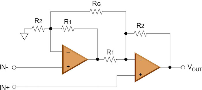
- Simplified structure
- Lower cost
- Still good performance
Trade-offs:
- Input impedance: Lower (but still high)
- CMRR: Slightly lower
- Gain range: More limited
- Cost: Lower
Use when: Budget is tight, moderate performance is acceptable
💎 Integrated Instrumentation Amplifiers
Instead of building from discrete op-amps, use dedicated ICs:
Popular IC In-Amps
| Part Number | CMRR | Gain Range | Features | Application |
|---|---|---|---|---|
| INA128 | 120dB | 1-10,000 | Low cost, general purpose | Sensors, bridges |
| AD620 | 100dB | 1-10,000 | Industry standard | Data acquisition |
| INA114 | 115dB | 1-10,000 | Ultra-low noise | Medical, audio |
| INA333 | 100dB | 1-1000 | Single supply, micro-power | Portable devices |
| AD8221 | 100dB | 1-1000 | Rail-to-rail, precision | Battery-powered |
🎯 Design Example: Pressure Sensor Interface
Sensor: Piezoresistive pressure sensor
Output: 0-100mV (0-10 bar)
Desired output: 0-5V
Component Selection:
In-Amp: AD620
- Low cost
- Excellent CMRR
- Easy to use
Gain needed:
For AD620, gain formula:
Solving for :
Use (exact value!)
Additional circuitry:
- 0.1µF ceramic caps on power pins
- 10µF tantalum for supply filtering
- Optional: Low-pass filter at output (anti-aliasing)
🛡️ Input Protection
Instrumentation amplifiers are sensitive. Protect them:
Protection Strategies
- ESD diodes: Clamp overvoltage to rails
- Series resistors: Limit current (1kΩ typical)
- RC filter: Remove high-frequency transients
- Zener clamps: Limit voltage to safe range
- Series resistors
- Zener diodes to ground
- Capacitors for filtering
⚡ Key Specifications to Know
Input Offset Voltage
Voltage at output when inputs are at same potential.
- Typical: 50µV to 5mV
- Precision: <25µV
- Effect: Adds DC error to measurement
Mitigation: Calibration, auto-zero techniques
Input Bias Current
Current flowing into/out of input terminals.
- Typical: 1nA to 100nA
- Low bias: <1nA
- Effect: Creates voltage drop across source impedance
Noise
Random voltage fluctuations.
- Voltage noise: 5-50 nV/√Hz
- Current noise: 0.1-10 pA/√Hz
- Effect: Limits minimum detectable signal
Bandwidth
Frequency range of accurate operation.
- Low power: 1kHz to 100kHz
- High speed: 1MHz to 10MHz
- Effect: Limits signal frequency
🔧 Practical Design Guidelines
When to Use In-Amps
✅ Use In-Amp when:
- Measuring differential signals < 100mV
- High CMRR needed (>80dB)
- High input impedance required
- Single resistor gain adjustment desired
- Bridge sensors (load cells, strain gauges)
- Medical/bio-potential measurements
❌ Don't use In-Amp when:
- Signals are already large (>1V differential)
- High speed needed (>1MHz)
- Cost is critical and simple diff amp sufficient
- Single-ended measurement (use regular op-amp)
Component Selection Tips
- Gain resistor: Use 0.1% tolerance, metal film
- Power supply: Use low-noise regulator, decouple well
- Input filtering: Add small cap (10pF-100pF) to reduce noise
- Output filtering: Low-pass for anti-aliasing before ADC
- Ground: Star grounding, separate analog and digital
🧪 Lab Exercise: Build a Weight Scale
Objective: Create a digital weight scale using load cell
Components:
- Load cell (strain gauge bridge)
- INA128 or AD620 instrumentation amplifier
- Arduino or similar ADC
- Power supply (±15V or +5V)
Steps:
- Connect load cell to bridge excitation (10V)
- Connect bridge outputs to In-Amp inputs
- Calculate and set gain () for 0-5V output
- Connect In-Amp output to ADC
- Calibrate with known weights
- Display weight on LCD/serial
Challenges:
- Zero offset adjustment (potentiometer)
- Temperature compensation
- Mechanical mounting
- Noise reduction
✅ Key Takeaways
- Instrumentation amplifiers are precision differential amplifiers
- Three op-amp architecture provides best performance
- Single resistor () sets gain
- CMRR is critical for rejecting common-mode noise
- High input impedance doesn't load sensors
- IC in-amps (AD620, INA128) are easy to use
- Essential for sensors, bridges, and medical applications
🎓 Looking Ahead
Instrumentation amplifiers are often used with:
- Wheatstone bridges (next topic!)
- Active filters (for noise reduction)
- ADCs (for data acquisition)
- Isolated amplifiers (for safety)
They're the foundation of precision measurement systems!
📚 Further Study
- Experiment with different gain settings
- Measure CMRR experimentally
- Interface with various sensors
- Study datasheets of commercial in-amps
- Learn about chopper-stabilized in-amps for ultra-low offset